
How to Power a COB LED Strip? A Commercial Sourcing Guide
When engineering a commercial lighting project, learning how to power a cob led strip safely is the first technical checkpoint。In modern commercial architectural lighting, indoor ceiling drop-tiers, and high-end retail display designs, dotless COB (Chip-on-Board) LED strips have rapidly become the premium linear standard. Their seamless, uniform light output completely eliminates the unsightly dark spots common in traditional SMD LED strips.
However, achieving flawless linear illumination requires precise electrical execution. In professional electrical contractor tenders and large-scale commercial linear lighting projects, improper powering schemes are the leading cause of field failures, severe voltage drops, and overheating.
⚠️ Critical Safety Note: Connecting low-voltage COB linear lights directly to a 220V or 110V AC household main power source will instantly burn out the FPCB circuitry, causing an immediate blowout hazard. You must use a dedicated driving power supply (also known as a transformer or adapter) to convert household AC power into low-voltage DC electricity.
As a specialized wholesale COB LED strip manufacturer, CS-TECH (operating a state-of-the-art 6,000 m² manufacturing hub) has compiled this comprehensive step-by-step engineering guide on how to safely and efficiently power COB LED strips.
1. Step 1: Verify the FPCB Specifications & Core Parameters
Before purchasing your power adapter, you must audit the technical data tags or architectural datasheets of your specific COB strip to confirm two critical parameters:
-
Operating Voltage: Commercial COB LED strips typically run on low-voltage DC currents—most frequently DC 12V or DC 24V. The output voltage of your power supply must match the strip’s voltage identically to prevent failure.
-
Total Power Calculation: Check the wattage rating per meter (e.g., 10W/m) and multiply it by the total runtime length of the installation.
Formula: Total System Wattage = Wattage per Meter × Total Length
2. Step 2: Sourcing the Correct Constant Voltage LED Driver
Because COB LED strips rely on built-in surface-mounted SMD resistors to limit current draw, they require a dedicated Constant Voltage LED Driver.
To guarantee that all components operate with maximum longevity and to prevent thermal overloading, always apply a 20% power safety margin (electrical redundancy). The rated capacity of your power supply must be at least 1.2 times the combined wattage of the linear lighting system:
Formula: Power Supply Capacity ≥ Total System Wattage × 1.2
This calculation is the baseline when evaluating how to power a cob led strip without overloading the circuits.
💡 Sourcing Selection Reference Table
-
1. Total System Wattage: Length × Wattage per Meter (Example: 5 m × 10 W/m = 50W)
-
2. 20% Overhead Multiplier: Total Wattage × 1.2 (Example: 50W × 1.2 = 60W)
-
3. Minimum Driver Rating: Match or exceed target power (Choose a 24V, 60W or higher Driver)
Power Supply Configurations:
-
Standard Indoor Applications: Specify open-frame or mesh-enclosed indoor power supplies.
-
Humid or Outdoor Architectural Sites: Always choose fully encapsulated waterproof drivers certified at an IP67 rating.
3. Step 3: Step-by-Step Electrical Connection Protocols
Always isolate the main breaker and cut off all 220V/110V AC grid currents before making structural wire splices to ensure absolute field safety.
-
AC Mains Input Connection: Connect the primary grid supply lines to the driver’s input terminal—splicing the Line input wire to the «L» terminal and the Neutral wire to the «N» terminal.
-
DC Output Connection to COB FPCB: Route the low-voltage output wires from the driver to the solder tabs of the COB strip. Attach the positive lead to «V+» (or «+») and the negative lead to «V-» (or «-«). Note: Reversing the polarity will prevent operation, but it typically will not damage the circuitry.
-
Insulation & Solder Integrity: If factory quick-connectors do not match your customized aluminum profiles, perform manual lead-wire soldering. Keep the soldering iron temperature below 300°C to prevent localized overheating of the phosphor layer, and seal all exposed joints with heavy-duty heat-shrink insulation tubing.
4. Step 4: Long-Run Systems & Segmented Powering Plans
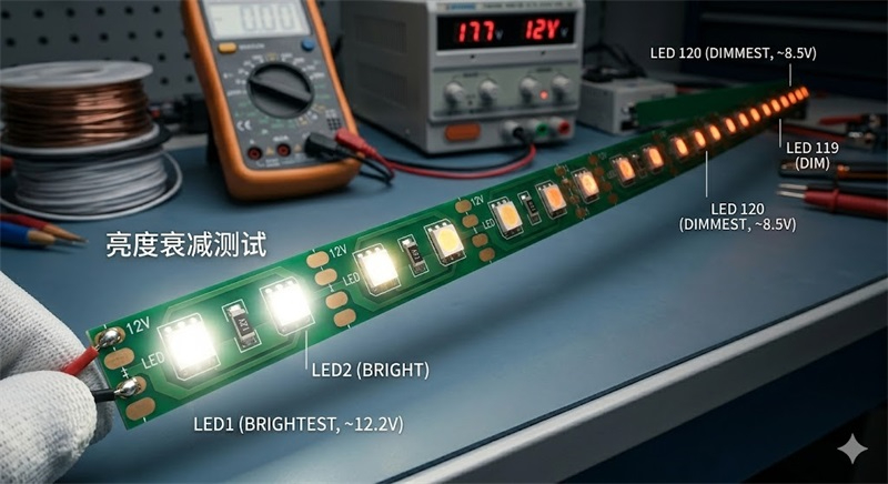
When an LED strip increases in length, the internal resistance of the copper traces within the Flexible Printed Circuit Board (FPCB) creates an electrical phenomenon known as Voltage Drop.
If a long-distance linear light is only powered from a single end, the trailing end suffers severe voltage loss. Many project failures during post-installation inspections are caused entirely by poor power distribution layouts rather than the quality of the strips themselves. High-density COB strips demand strict voltage stability.
Why Long-Distance Single-End Runs Fail:
-
Tail End Dimming: The trailing end of a long single-feed run appears visibly dim or loses luminosity.
-
Color Discrepancy: In RGB or tunable white strips, lower voltage at the tail end causes noticeable color shifting.
-
Localized Heat Generation: Current concentration at the front-end traces increases circuit and solder point temperatures, accelerating degradation.
-
Unstable Operation: Severe voltage drops lead to visible flickering or localized diode dropouts.
To maintain perfectly uniform brightness and safe low-heat operation, a Segmented Powering Plan / Multi-Point Injection Layout is highly mandatory.
[Single-End Feed - INCORRECT for Long Runs (>10m)]
Driver (+) --------------> [======= COB LED Strip =======] (Dim/Color Shift at Tail)

[Dual-End Feed - RECOMMENDED for 5m to 10m]
Driver (+) |------------> [======= COB LED Strip =======] <------------| Driver (+)
           |___________________________________________________________|

[Parallel Loop / Mid-Point Injection - RECOMMENDED for Long Runways]
Driver (+) |------------> [=== COB Segment 1 ===] <---|
           |------------> [=== COB Segment 2 ===] <---| Main DC Header Trunk Cable
Voltage Choice & Maximum Single-Ended Run Limits
-
DC 12V COB Strips (Up to 5 Meters): Compact retail displays, cabinet task lighting, vehicle accents.
-
DC 24V COB Strips (5 to 10 Meters): The commercial project standard for tenant fit-outs, hotel coves, and office spaces.
-
DC 36V / 48V COB Strips (Over 10 Meters): Specialized long-distance infrastructure projects, bridge handrails, and landscape lighting.
To clear up common field issues regarding how to power a cob led strip, our engineering team has summarized these top contractor questions:
5. Frequently Asked Questions (FAQ)
Which is better for long commercial runs, a 12V or 24V COB LED strip?
24V COB LED strips are significantly better for commercial applications. Because a higher operational voltage reduces the overall current draw, a 24V system experiences half the current of a 12V system for the exact same wattage output. This drastically cuts down on FPCB voltage drop, minimizes tail-end dimming, allows for much longer single-feed runs, and cuts material costs by allowing thinner supply wires.
Can I plug a low-voltage COB LED strip straight into a standard wall outlet?
No. Standard household wall outlets output high-voltage AC electricity (typically 110V or 220V), whereas low-voltage COB LED strips require regulated DC electricity. Connecting a low-voltage strip directly to standard household mains will instantly blow up the FPCB circuitry, burn out the chip matrix, and pose an immediate fire hazard. You must always place a certified constant-voltage LED driver between the AC outlet and the strip.
What is the ideal wire gauge to prevent voltage drop between the driver and the COB strip?
The ideal wire gauge depends on the total current draw and the layout distance of the run, but for most professional commercial linear lighting projects, 16 AWG or 14 AWG stranded copper wire is highly recommended for supply header lines. Using wiring that is too thin increases circuit resistance, multiplying your voltage drop before the electricity even reaches the FPCB traces. For long-distance setups, always use a parallel loop distribution plan.
How do I troubleshoot a COB LED strip that flashes or strobes upon power-up?
If a COB strip strobes or flashes immediately after power-up, it is typically a sign that the LED driver’s over-current protection has been triggered. This occurs when the total wattage draw of the connected strip exceeds the maximum rated output of the power supply, or when a minor short-circuit exists along the cut joints or solder pads. Verify your total system wattage and replace the power supply with a driver that provides at least a 20% power redundancy margin.
6. Secure Supply Chain Certainty with CS-TECH
Powering architectural-grade linear lighting requires precision components and deep electrical expertise. At CS-TECH, operating from our 6,000 square meter modern manufacturing hub, we bring 15 years of rigorous engineering experience to global B2B clients.
As a certified National High-Tech Enterprise, our complete range of commercial COB LED strips and matching drivers carry full global safety certifications—including UL, CE, and SAA compliance. We fulfill bulk wholesale procurement contracts with advanced engineering support, ensuring zero color shift and perfect uniformity across massive installations.
Need engineering samples for your lighting mock-up, custom layout wiring diagrams, or specialized commercial pricing tiers? Contact our technical consulting team today to ensure error-free, brilliant illumination for your next B2B project!